Simple Starter Motor Diagram
This diagram is for 3 phase reversing motor control with 24 vdc control voltage. Simple starter wiring diagram.

Starter Solenoid Wiring Diagram Ignition Motorcycle Wiring Car Alternator Alternator Working
Also read about the speed torque characteristics of these motors along with its different types.

Simple starter motor diagram. The dol starter comprises an mccb or circuit breaker contactor and an overload relay for protection. Electrical checks are made with a circuit tester or test lamp or with a voltmeter. A direct online starter consists of two buttons a green button for starting and a red for stopping purpose of the motor.
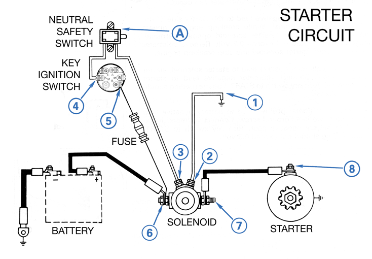
Ignition switch the starter is turned on by the ignition switch s sol solenoid position. 2 starter solenoid the starter solenoid is the main part of the control starter circuit including the with relay type. The starter system is simple and the checks on it are straightforward.
It uses two contactors two auxiliary contact blocks an overload relay a mechanical interlock two normally open start pushbuttons a normally closed stop pushbutton and a power supply with a fuse. It is a momentary contact position usually on the key switch. Merely ignore the control wiring in red 3ph starter 3ph motor reversible.
A mechanical check to see if the starter pinion gear. Figure 1 is a typical wiring diagram for a three phase magnetic motor starter. The circuit breaker is used for protection against short circuits while the overload relay protects the motor from overloading.
The contactor is used for starting and stopping the motor where the green and red buttons are connected. Assuming you ve got an electric ignition it s just a matter of wiring the start button the starter solenoid and the starter motor into the loop. Learn how a capacitor start induction run motor is capable of producing twice as much torque of a split phase motor.
Based on the above wiring diagram you need the following. If the starter does not turn the engine although the car battery is in good condition the fault may be a simple mechanical one or it may be an electrical one in the starter motor circuit. Line 1 l1 t1 motor 1 l1 hot 240v or neutral 120v line 2 l2 t2 l3 t3 motor 2 l2 hot 120v or 240v manual starter.
3 typical car starting system diagram 1 ignition switch usually the ignition switch connects with a key or a button and inside of it has the regular wire. The wiring diagram for a dol stater is shown below. The dol starter is made of a circuit breaker or mccb or fuse an overload relay and contactor or coil.
Figure 1 typical wiring diagram line diagrams show circuits of the operation of the controller line diagrams also called schematic or elementary diagrams show the circuits which form the basic operation of the controller. There s plenty of diagrams you can find online for this and probably plenty for the trail boss specifically but it d look something like battery starter button solenoid starter. Click here to view a capacitor start motor circuit diagram for starting a single phase motor.
Wondering how a capacitor can be used to start a single phase motor. Wiring up the starter motor circuit is rather simple. Dol starter wiring diagram.

Starter Solenoid Wiring Diagram Deltagenerali Me Within Ford F150 Ford Remote Car Starter

Small Engine Starter Switch Wiring Diagram And Basic Ignition Switch Wiring Diagram Wiring Schematic Diagram In 2020 Switch Ignite Diagram

16 Motorcycle Starter Relay Diagram Motorcycle Diagram Wiringg Net In 2020 Electrical Circuit Diagram Car Alternator Alternator

10 Small Engine Starter Switch Wiring Diagram Engine Diagram Wiringg Net In 2020 Boat Wiring Trailer Wiring Diagram Kill Switch

Starter Solenoid Wiring Diagram Starter Motor Ford Tractors Starter

Smart Car Starter Motor Wiring Diagram Model T Ford Forum In Boat Wiring Mercury Outboard Electrical Diagram

Small Engine Starter Motors Electrical Systems Diagrams And Killswitches Small Engine Starter Motor Engineering

How To Use Voltage Drop To Troubleshoot The Starter System Car Insurance Engineering Tractors

Perfect Ford Alternator Wiring Diagram Internal Regulator Starter Wiring Diagram With Regulator Wiring Diagramstarter Wi Starter Motor Small Engine Engineering

Starter Diagram Motorcycle Wiring Automotive Mechanic Automotive Repair

Gm Starter Solenoid Wiring Diagram Post Date 07 Dec 2018 78 Source Http Moesappaloosas Com Wp Automotive Repair Truck Repair Automotive Mechanic

60 Beautiful Motor Starter Wiring Diagram In 2020 Electrical Circuit Diagram Circuit Diagram Electrical Projects
Pin On Diy

Starting System Diagram Starter Motor Automotive Repair Motorcycle Wiring

Engine Run Stand Wiring Diagram Images Engineering Diagram New Engine

Starting System Diagram Starter Motor Automotive Repair Motorcycle Wiring

50 Awesome Weg Motor Starter Wiring Diagram In 2020 Electrical Wiring Diagram Air Compressor Pressure Switch Circuit Diagram

Basic Car Parts Diagram Illustrated Diagram Of A Basic Internal Combustion Engine Automotive Engineering Automotive Mechanic Combustion Engine

Simple Small Engine Wiring Diagram In 2020 Electrical Diagram Diagram Kohler Engines